If your key does not output anything at all, it may be a loose or missing diode. If you haven't tried cleaning your socket and repairing your socket, do these first, unless you can clearly see the diode is the problem.
Reminder: This process will void your warranty. Do not attempt this if you are still within the warranty period for your board. If you are still within your warranty period, email us instead.
Each key on our keyboards (and many others) has a diode. These are electrical components that force electricity to flow in one direction which is very useful for keyboard matrixes. Without diodes, a keyboard is easily "confused" about what key you actually meant to press, especially when going quickly. For our purposes though, a loose or missing diode usually means a key won't work at all.
Warning: This process is one of the harder things covered. It requires very precise soldering and patience. It is completely possible, but it may be difficult and frustrating even for more experienced solderers. Just relax, take your time, and be willing to attempt this several times before getting it right.
You will notice that the diodes we use on our boards are extremely small. This is not an easy component to source, so try not to lose them if one has come off completely. If you do lose a diode though, things may still be salvageable.
Also, note that diodes are directional. They must be installed facing the correct way to work. The directionality of diodes is usually indicated with a thick line on one end of them, and the footprint on our boards has a matching thick line to help remind you which way is which. Depending on the diode used, the directionality indicator line may be very subtle, but you will be able to see it by looking carefully.
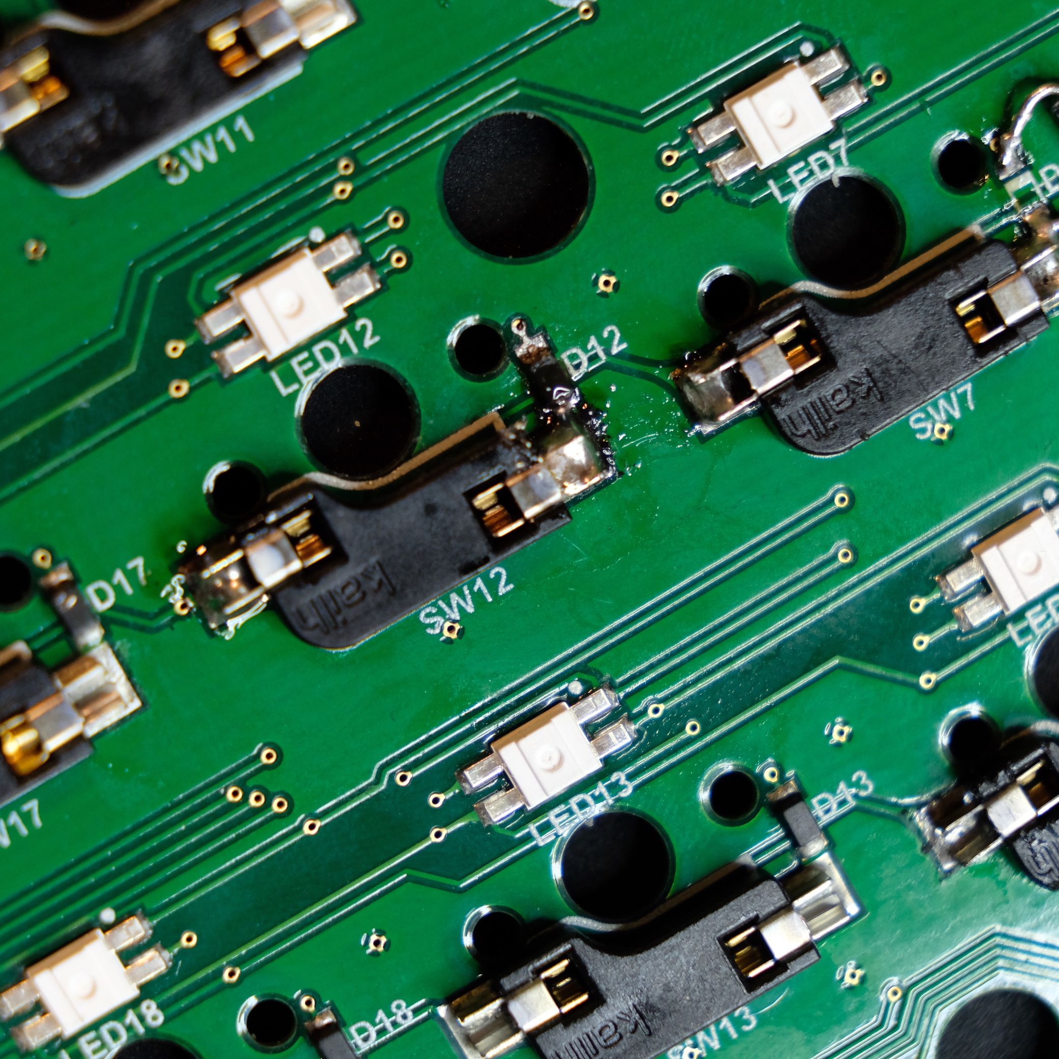
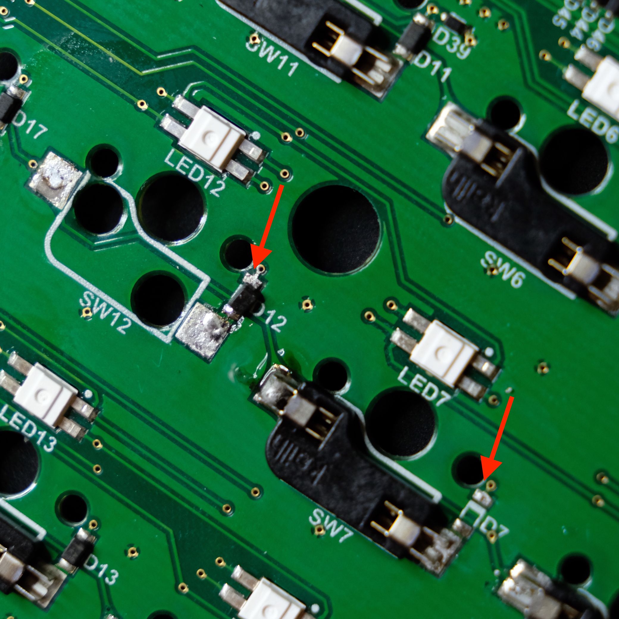 Here I have purposely loosened the diode at SW12 and removed the diode at SW7 for demonstration purposes. For extra authenticity, I dropped the removed diode into my rug. Will I ever see it again? Unlikely. :)
What's important is this can still be fixed.
Repairing a loose diode
This is the far more likely scenario. It's possible that a diode may come loose (usually on one side) over time if the original soldering wasn't as solid as it could have been and the board is knocked into something.
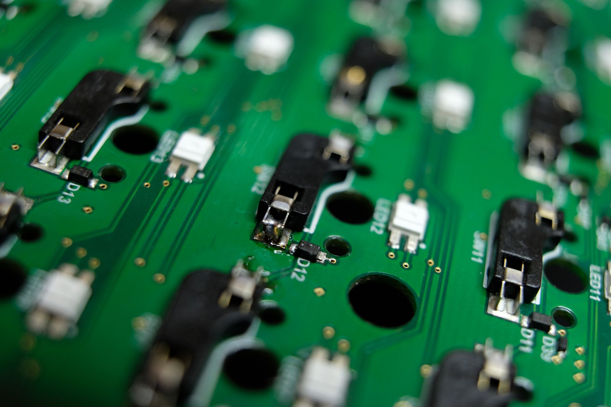 I can tell this diode is loose because I can see one of its small contacts sitting on top of the solder instead of inside it. This is a somewhat exaggerated example to help show up on camera better, but if you have a similar problem, you should be able to see something along these lines by carefully inspecting it in person. This fix is very, very delicate.
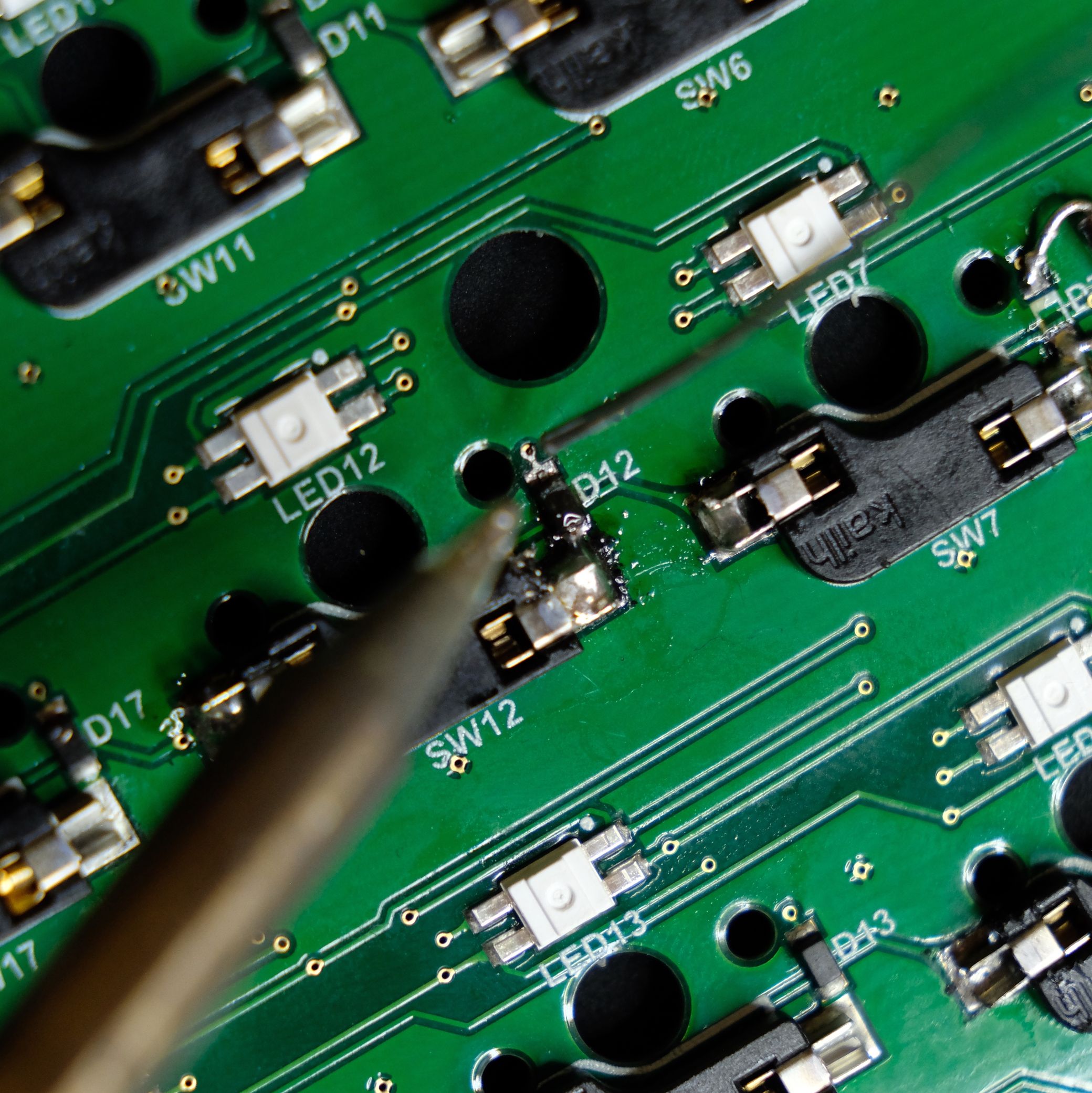
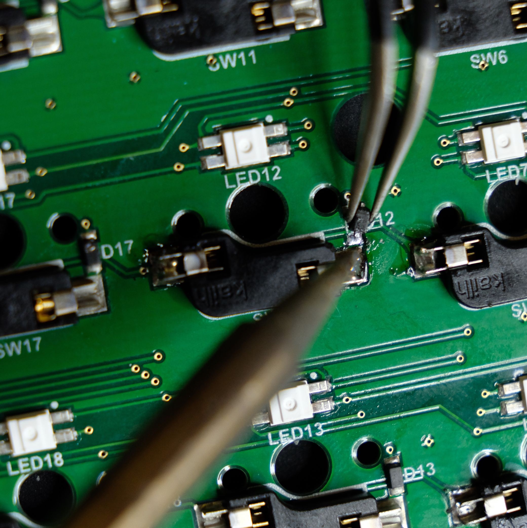 Here I am heating up the existing solder while adding a tiny bit more just to make sure I can make a good connection. I show this as kind of a worst-case scenario (like maybe you're not sure which end of the diode is loose or it has come off completely), but I actually would not recommend doing this just yet if you can avoid it. As you might be able to tell from this picture, it's quite easy to heat up the "good" end of the diode and move it out of position or off the board completely.
Instead, try to figure out which end of the diode has come up, and focus on just resoldering that end while leaving the good end intact to help keep the diode in place. That will make this much easier.
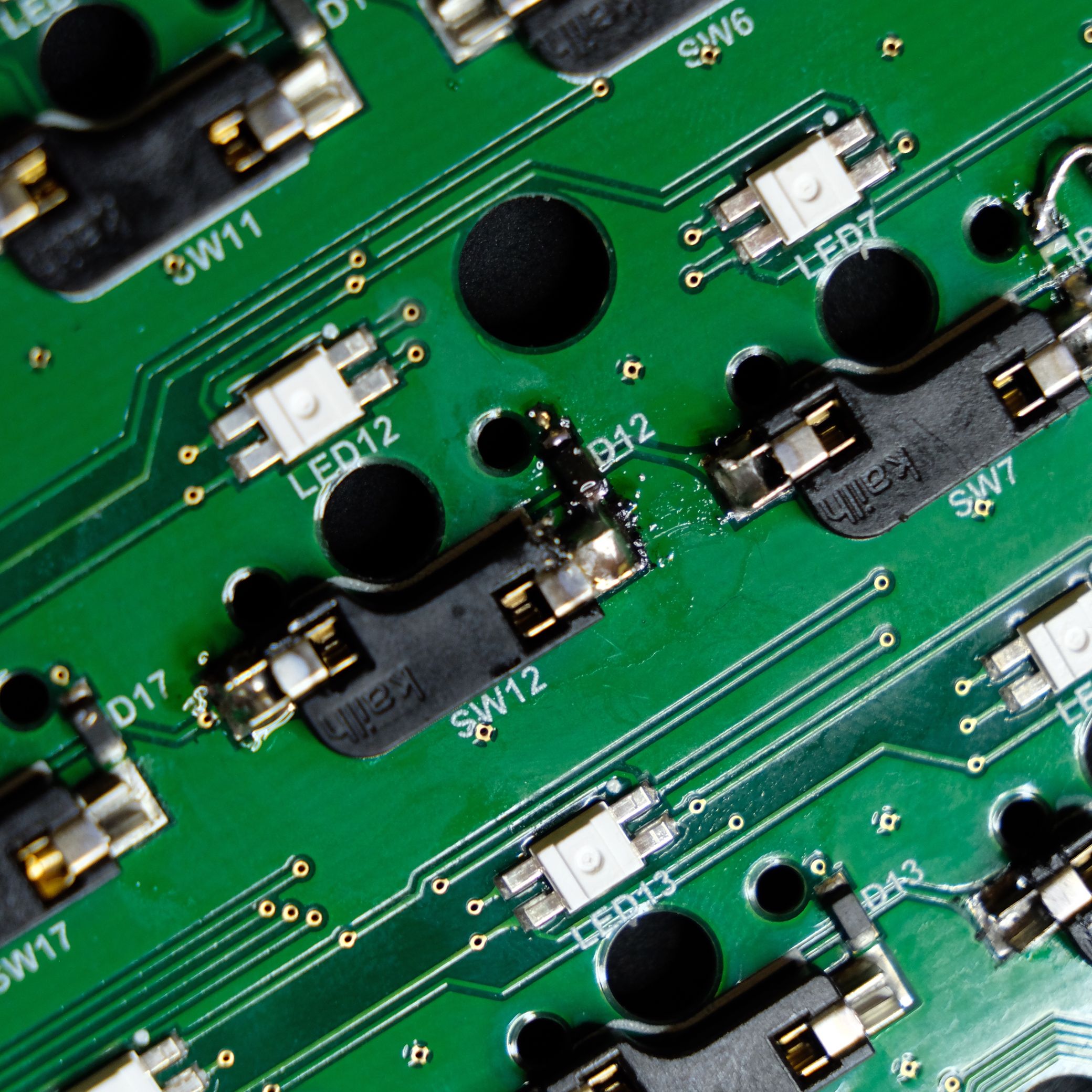
 After some struggle, it's done. The diode is now resting nicely in the footprint and one end is very well secured. It looks a bit more gruesome than it really is, although the hotswap socket did get a bit singed by the soldering iron. I'm purposely using a non-ideal soldering iron tip here to show that it can be done, but if you have a sharper tip, that will also help a lot.
 Now, it's just a matter of adding some more solder to the other end. This is easier, but we're still dealing with a very small part, so take it slow.
 Done! Thankfully, the board's case will hide this fine work.
Repairing a missing diode
This seems like the worst case scenario: you're missing a diode and you have no idea where it is. Fear not, we can still repair this. It's actually slightly easier than reattaching one of the stock diodes that has come off.
 This is a different kind of diode, called a through hole diode, that is much more available. The default diodes are called SMD (Surface Mount Device), but it's not enough to just get any SMD diode because they come in tons of different sizes, and too big or too small of an SMD diode won't work. A through hole diode is more flexible.
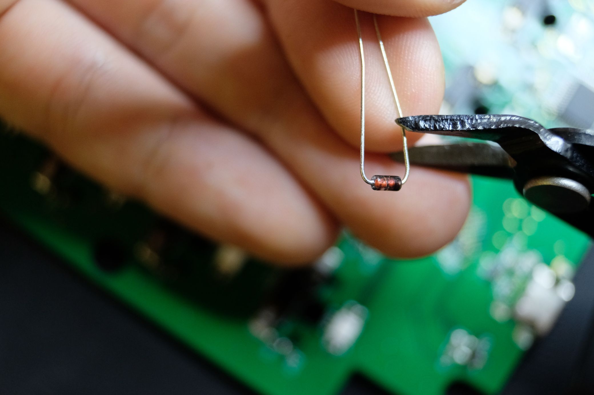 Of course, the diode is much too big in its current state. We'll need to cut the legs down. This is normal with through hole diodes even when using them how they're intended to be used, though, so no need to worry about ruining anything. This image also gives us a good look at the diode's directionality indicator: that black line on one side. This should match the thick line of the diode footprint on the PCB.
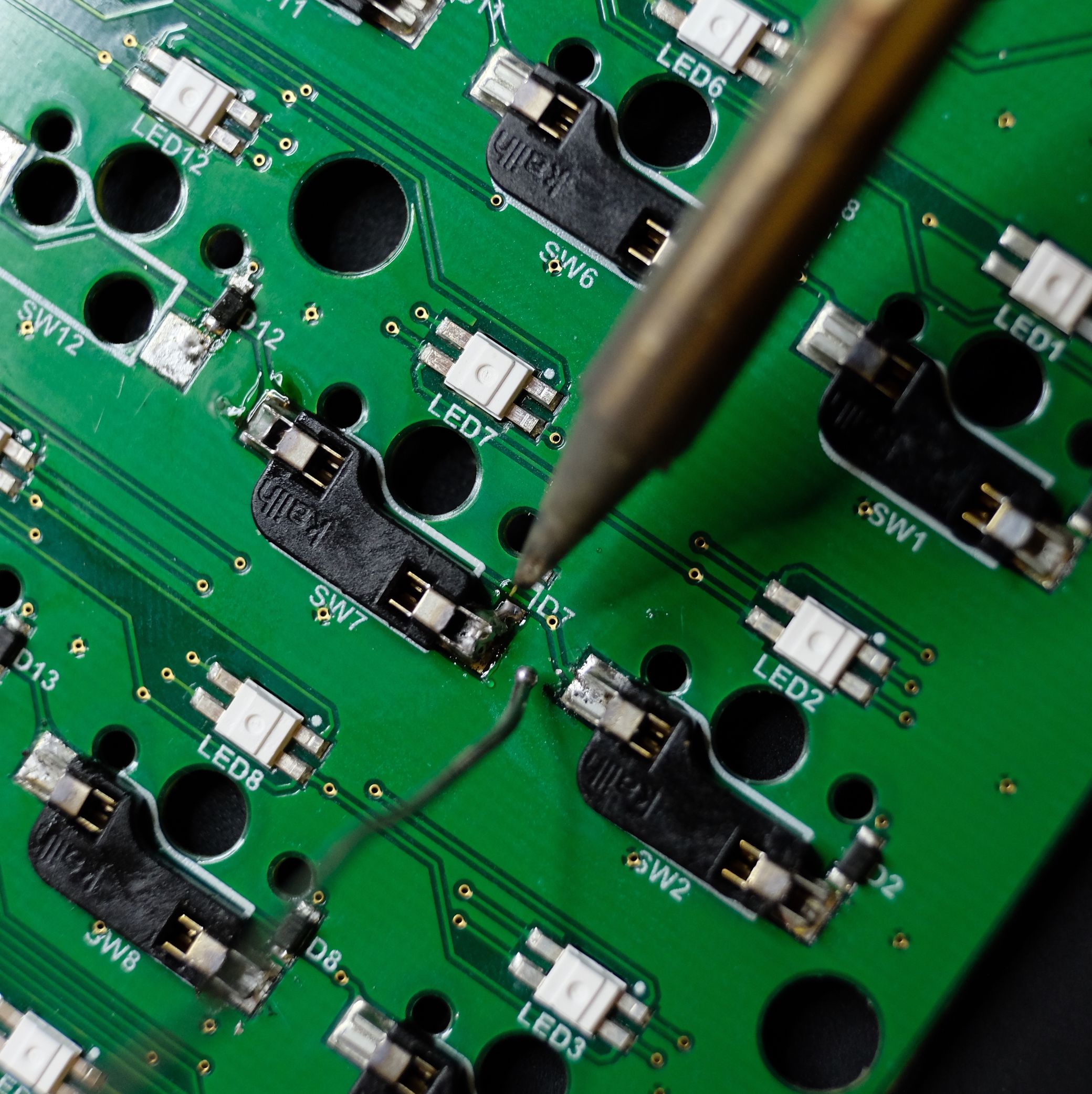 Once things are mostly trimmed, we can follow pretty much the same procedure we have been. First, we'll want a small pile of solder on one side. This is much easier now that there's no SMD diode threatening to pop off.
 Then, heat up the pile of solder and push one leg of the diode in so it's nicely inserted. You'll also want to make sure the diode is as flat against the PCB at possible, and that it's not lined up with any hotswap sockets. There are supports in the cases of our boards that will interfere with the diode if it's on the same line as a socket.
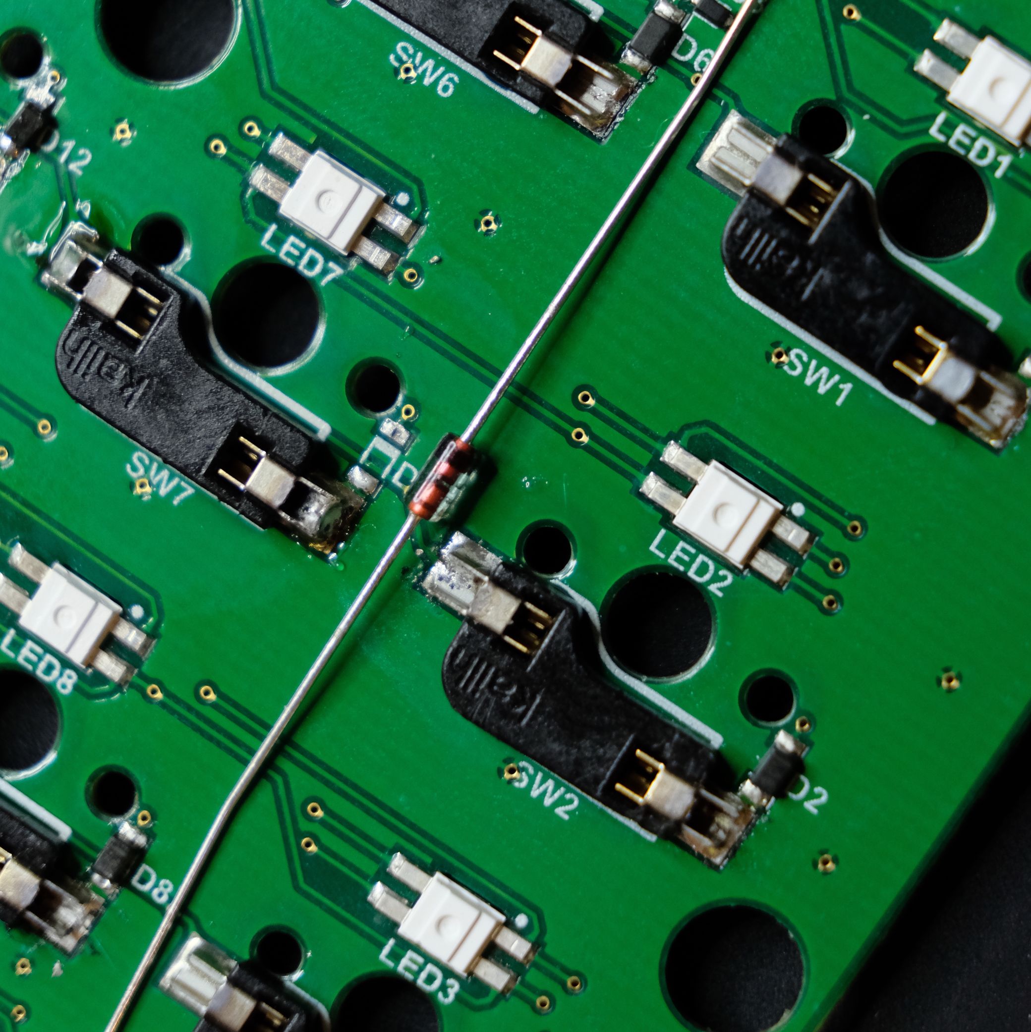
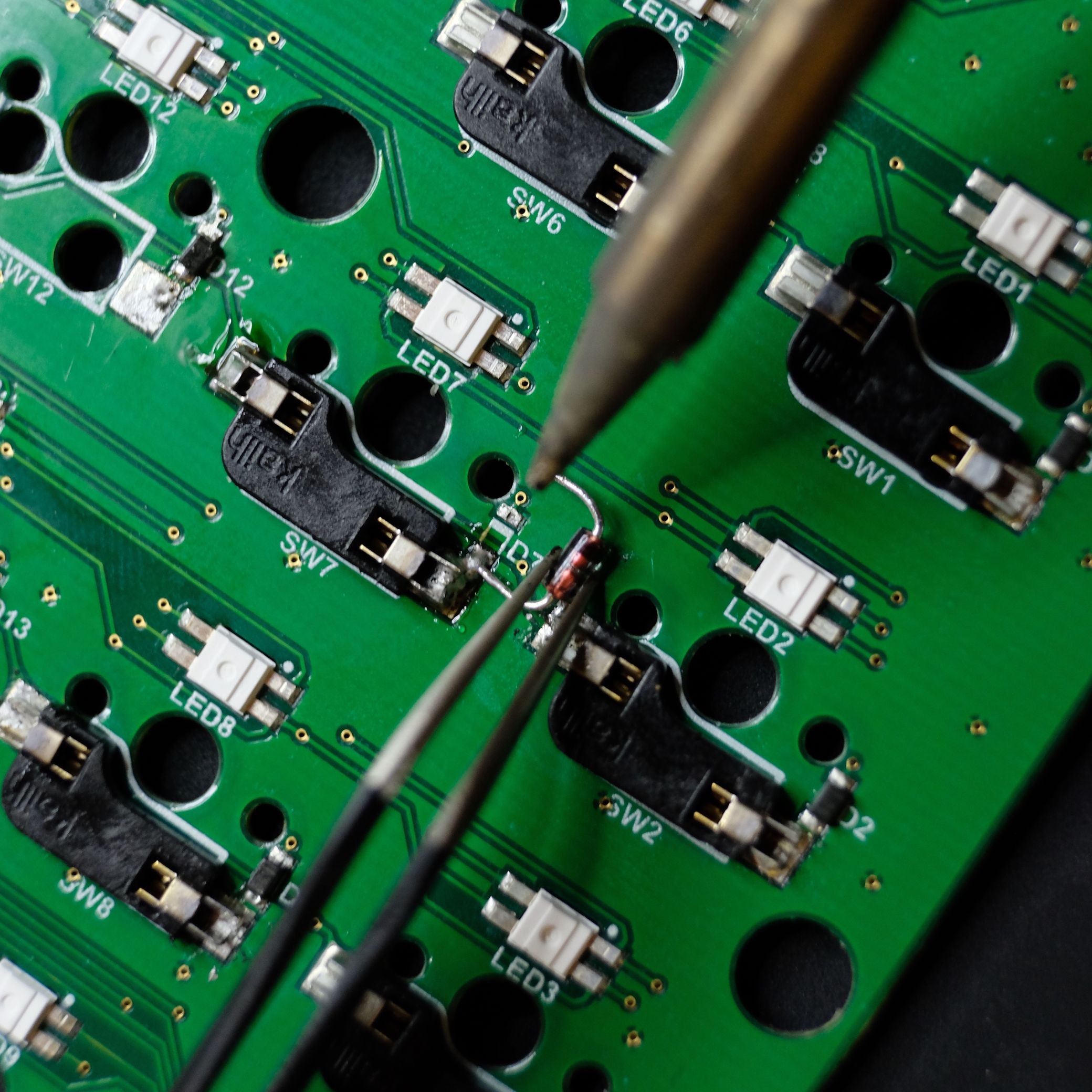
 With one side secured, we can do any final trimming of the other side and repeat the same procedure: pile the solder, heat it up, and push the leg in. One leg of the diode looks very close to contacting the nearby socket (SW2) here, but it's got some space if you see it in person. Still, I would probably try to get your diode legs just a little bit shorter here to be on the safe side.
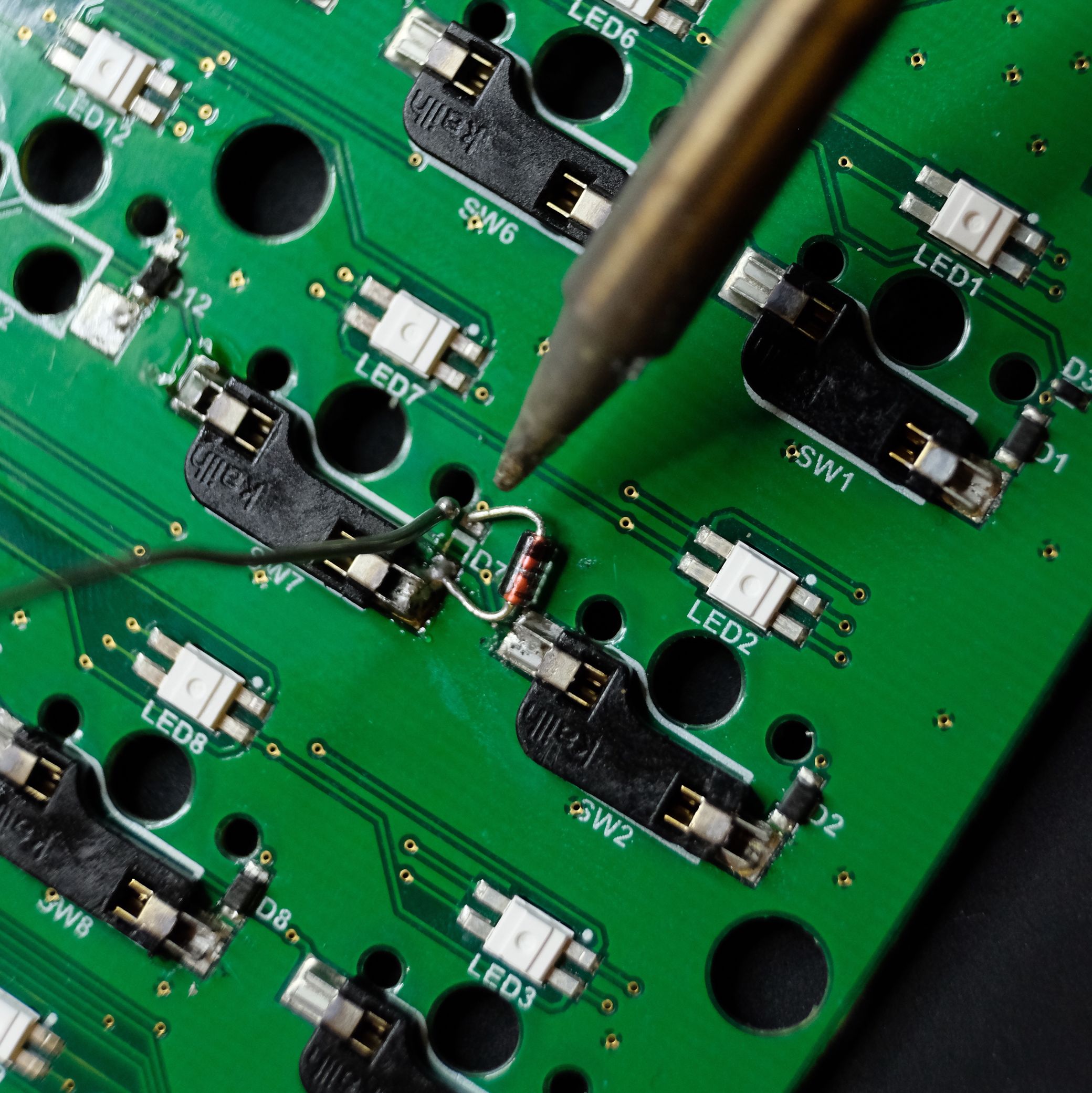
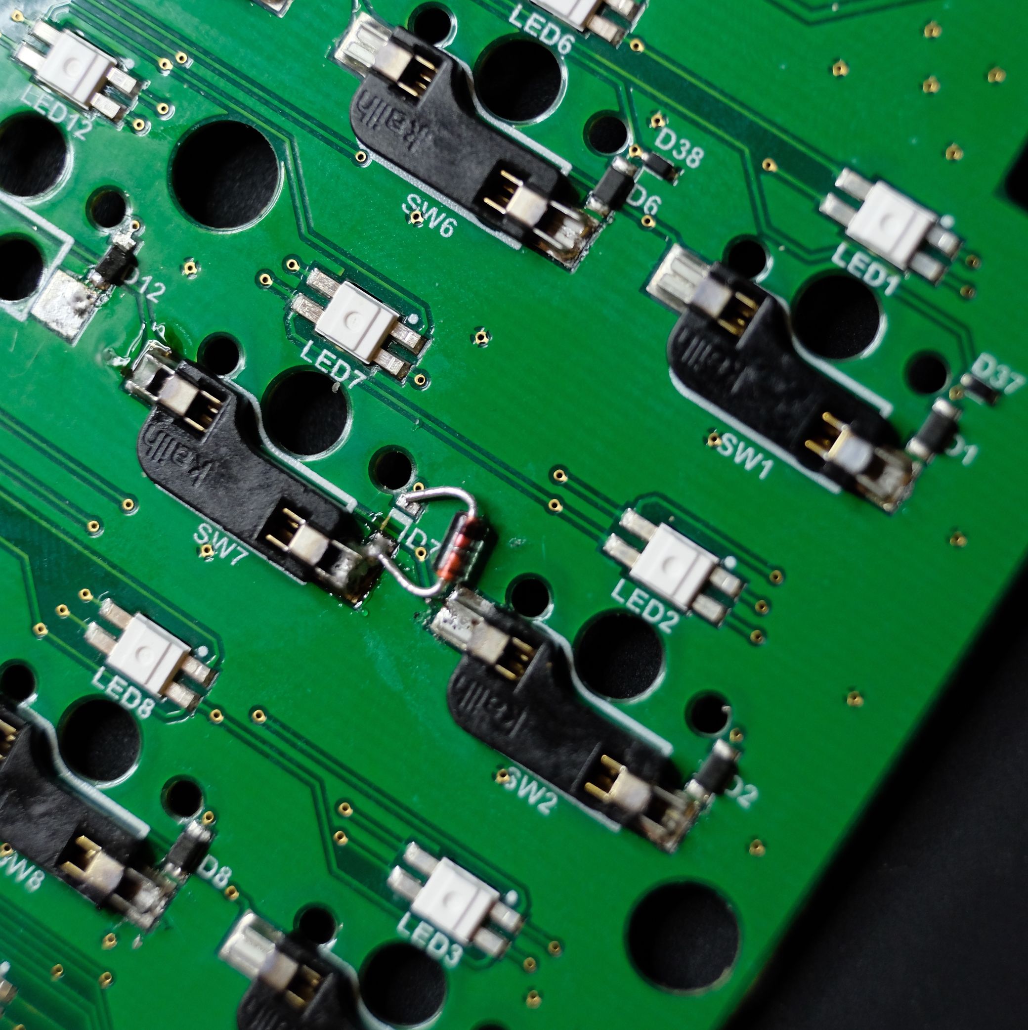 Woo! It works. Just like before, the board's case will hide this strange new component nicely.