The Saucer is my DIY trackpad for the Voyager. This is just a personal passion project I wanted to share — not an official ZSA product (though ZSA might create an “official” Voyager pointing device at some point that might be quite similar to the Saucer!).
Update: We did indeed make an official ZSA product, called the Navigator. It's a whole system. Check it out!
The following article is basically my "behind the scenes" design process. I think (hope) it's interesting, but if you'd like to just dive into building a Saucer for yourself, here is the build guide.
For day to day work, I usually use an Apple trackpad. I've experimented with trackballs and traditional mice, and I've used several that I like, but it's hard to match the appeal of one simple slab for all my mousing needs. There are just two problems with the Apple trackpad for me.

I have two cats that absolutely love to stand on my desk and request (demand) pets while I work. They try to be fairly considerate by not standing on my trackpad, but it still happens. The most common annoyance is when they sit down and graze the edge of my trackpad with their bodies, making any of my attempts to mouse around register weirdly until I notice and move the trackpad away.
I was getting fed up with this, and there is simply no way to completely refuse my cats access to my desk, so I started thinking about alternatives.
I had seen some implementations of a Cirque trackpad on other DIY split keyboards that I was always curious about, but I never tried one myself. When I found out the right side of the Voyager exposed I2C pins, it seemed like the perfect chance to try my hand at a Voyager trackpad.
Proof of concept
First, I needed to make sure the idea would work at all. I learned the back pins on the right half of the Voyager were broken out for I2C like so:
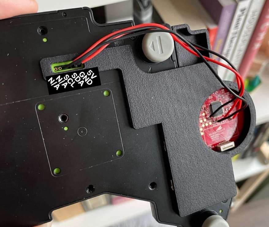
Wiring it was easy enough, and after a little fiddling with the firmware, it worked!

Okay, so I knew this was at least possible. I decided to make a real project out of this idea (assuming the whole thing worked) and release a guide. I wanted to make a "real" Voyager accessory — something that, while still obviously DIY, would be appealing and functional. Basically, I wanted to get as close to official ZSA quality as I could while still making it practical to make with some basic tools.
Pogo pins
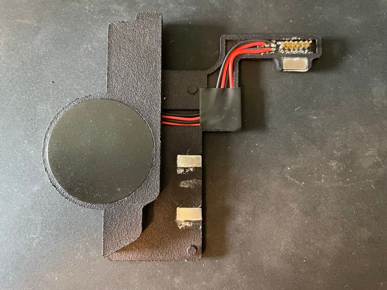
My first take on the idea was pogo pins, small spring-loaded connectors. I wanted to attach the trackpad enclosure to the Voyager magnetically and use pogo pins to make contact with the exposed points on the back of the board.
I worked at this design for a long, long time. I looked through pages upon pages of different pogo pins, took dozens of measurements, and went through many revisions before producing anything physical. I decided I would need a small custom PCB that I would solder the pogo pins to, then I would connect that PCB to the trackpad, and the enclosure would be a nice, self-contained part.

This project was also the major reason I picked up 3D modeling again and started to learn how to use Plasticity. I had never actually modeled for 3D printing, though, so that was an interesting challenge. Finally, after checking and rechecking my designs, I ordered all the parts, assembled it, and... it worked!
I was really happy — this was hours upon hours of work realized as a real working thing. I'm not ashamed to admit that I spent a while just connecting and disconnecting it over and over.

As happy as I was though, I now had a problem. Honestly, I was never confident that I'd be able to pull this design off, so I had a bit of tunnel vision on making it work. Even though I did it, I had to realize that that, ultimately, this couldn't be the design I released.
The biggest problem is it would only work for the right half of the Voyager. The exposed pins on the left half of the keyboard do not break out into I2C lines — they're entirely different for internal testing. I considered releasing this version as a right-half only design, but that seemed like a significant drawback for anyone who prefers to use a mouse with their left hand.
For a while, I tried to solve this by designing another even smaller custom PCB that would attach internally on the left side to mimic the right side's pinout, but after doing some testing with this, it only made another issue worse: complexity.

I wanted this project to feel doable for even a relative novice to soldering and QMK. Getting custom PCBs made and soldering everything together (especially the pogo pins) was difficult. It's certainly doable, but I worried that it would just be too much of a barrier to entry.
So, I went back to the drawing board.
Going through TRRS
After talking with both Erez and ZSA's QMK liaison, Drashna, about this, I realized the solution was right in front of me all along: the TRRS port.
ZSA boards already use the I2C protocol to connect the secondary half of the keyboard to the main half using a TRRS cable. I2C is a neat protocol because you can connect many separate peripherals through a single connection, as long as they have unique addresses. This meant I could insert the trackpad connection at any point in the TRRS connection (on the left or right half) and it would work while still allowing the main half of the board to communicate with the other half. The aesthetic wouldn't be quite as clean as the previous version, but it would be far more versatile and easier to make. I started prototyping again.

This was definitely the easier route. I took a TRRS splitter and connected one end of it to the trackpad, then plugged everything else into the board, and it worked right away.
My last order of business was to simplify further. I was happy with the design already, but I wanted to add even more polish and make it as straightforward as possible.
I started asking myself what the most necessary, fundamental aspects of the design were. Why glue magnets in when the Voyager already comes with magnets? Why have a weird fragile cable channel when there's already a part of the design that would work? I would keep what was needed and throw everything else away.
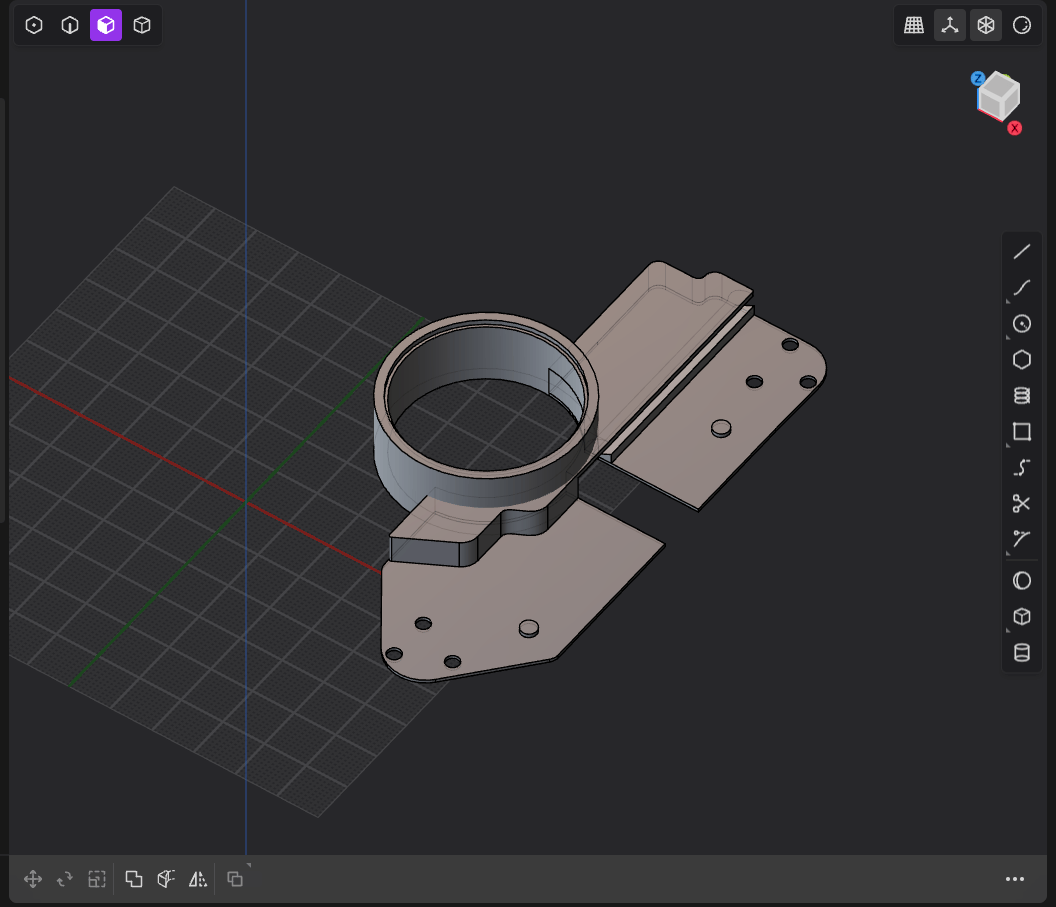
Eventually, I ended up with a very simple enclosure with no need to glue or route cables in any special way. I also raised the trackpad up to be more in line with the top of the Voyager keys, which is way more comfortable. The most straightforward things are often the hardest to come up with. This is the design you'll find in the build guide.

I've been using this design for the last few weeks, and I'm enjoying it. There is a bit of a learning curve that you may not expect. Even the largest Cirque trackpad is a small surface. Dialing in the right speed settings to make it feel right was tricky, and as I get more used to it, I think I'll need to tweak it further (and, should you make your own Saucer, you’ll have to find your own optimal settings). The small surface area also means I wouldn't really recommend this for creative work or anything super mouse-heavy. It's great for workflows that involve a mix of typing and mousing like coding, writing, spreadsheets, general office work, etc. If you need very precise and consistent mouse control, though, you're still better off with a dedicated mouse.
I also have some thoughts about how I can make the wires of the enclosure more aesthetically pleasing that I will share as an optional step on the build guide if I'm successful.
Above all else though, I'm proud to have made something. I had a vision, refined it over many hours, and created something new. If you give the Saucer a try, I hope you like it, too.