A quick intro from Erez: When Kevin wrote to ask if he could hack a Trackball onto the Moonlander, I answered "basically no" (you can see a screenshot of my answer below). Then he went and did it anyway — and so beautifully, that I just had to ask him for a complete writeup of his adventure. Kevin replied with a wonderfully deep technical dive documenting the journey. This is how you void your warranty with style. :) Lightly edited, and without further ado, I give you Kevin:
There’s a great meme out there where certain people love to spend hours automating some repetitive 5 second task, with the false assumption that it will save more time in the long run. I have never seen a meme so thoroughly describe my brain.
My job as a programmer has me constantly searching for inefficiencies in systems, finding little problems. A problem can cost a few extra microseconds, but when repeated thousands of times over, it can cost minutes. If your app or program takes minutes to respond, you uninstall it.
When my brain is wired to see these mirco-inefficiencies, I can’t help but notice certain things, like moving my hand over to my mouse, then having to move my hand back to my keyboard, look for the home row, find it, and start typing again.
My initial solution was simple: moving to the mouse is inefficient, so maybe I should just figure out how to use the mouse less. I leaned heavily into VIM, and VIM emulation in everything. I installed Vimium, so I can use the keyboard to drive my web browser. I installed Homerow on my Macbook so I could have Vimium everywhere. I’ve installed the VIM plugin for my work IDE, and fully utilize it and all the shortcuts available.
However, there’s always something that requires a mouse, and I was still experiencing the constant tingling frustration that I could be faster, if only I could remove the need to reach for the mouse.
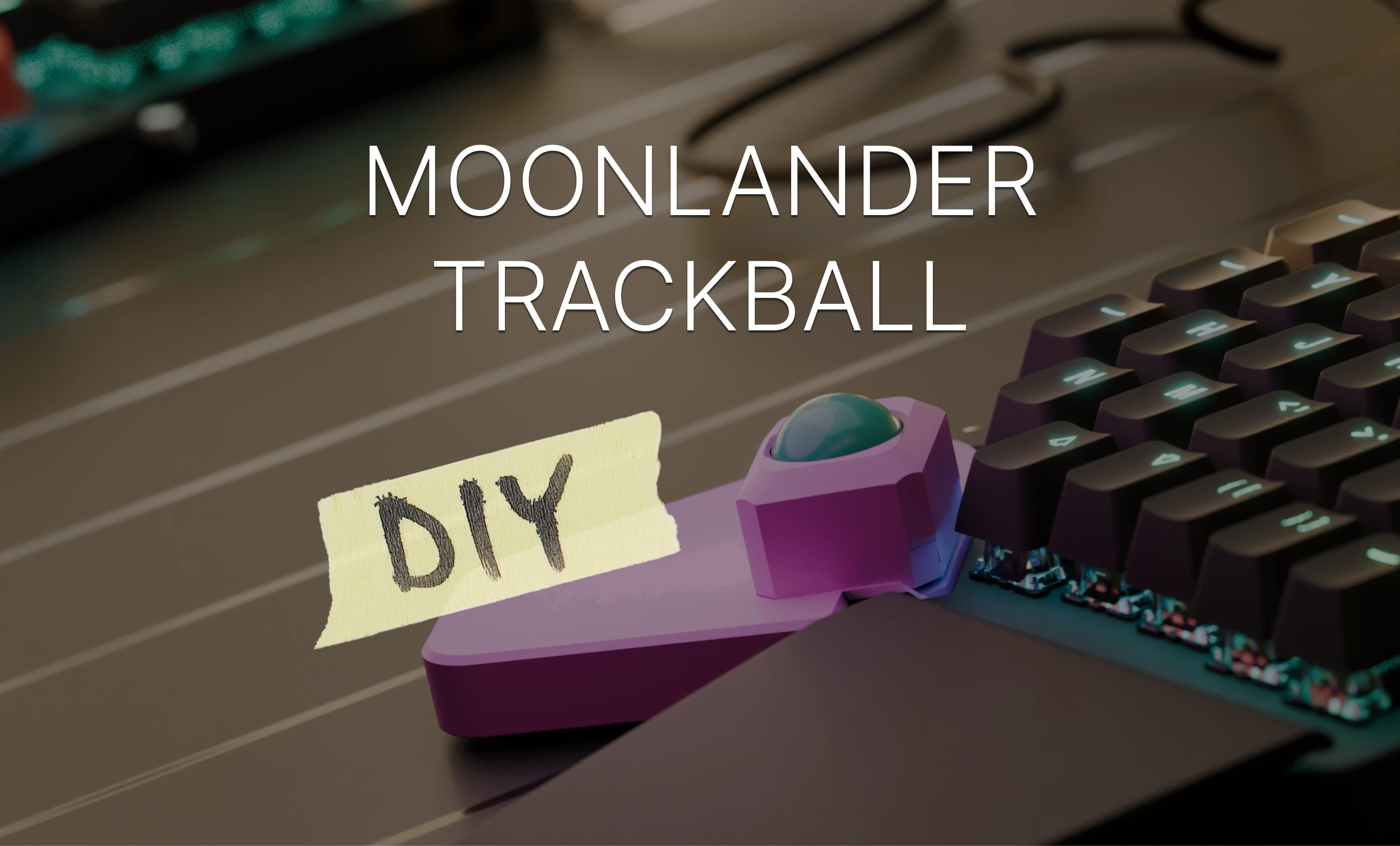
This “problem” was what led me on an almost 3 year journey to eventually create what I’ve been calling the “Moonrover MK2” (carried by the Moonlander, it’s a smaller thing that can “move”).
The Long Way ‘round
I decided to start building my dream keyboard, but wanted to go a “safe route” by not trying to do too much at once.
Someone at work had a Kinesis Freestyle that they were getting rid of, and I started there. I cut out the right spacebar (luckily, it didn’t mess with the electronics) and added a trackball in.
To get the trackball, I found a handheld presentation mouse that had a trackball built into it. I extracted the sensor and the ball and placed it where the right spacebar had been on my keyboard.
I then spent a good year (or more, it’s all a blur) on occasional weekends trying to see if I could make things more compact so that it could fit into the keyboard. I planned to 3D print a new housing to fit everything together as a single portable unit.

Eventually, I found out about the PMW3360, and found a breakout board online that let me finally get the “trackball” down to a reasonable size.
The main limitation was the distance required between the sensor and the ball. Luckily, things lined up such that if the back of the sensor was directly against the desk, the trackball was right about at key height.
After another year of occasional tinkering, I finished my “Franken-Style”, with a built in trackball. I knew the idea “worked”:

It had so many problems:
-
It was beyond ugly. I knew I wanted to eventually build a housing for the top, but the existing top was full of fancy chamfers and key cutouts. Copying it all to look even somewhat put together would be a ton of work.
-
It didn’t run any custom firmware. While my mouse was super configurable to do exactly what I wanted (including implementing my own special take on drag scroll, which I only learned was a thing much later), the keyboard itself had a ton of useless macro buttons (especially when connected to a Mac) and there was no way for me to change that.
-
The mouse was forever a second peripheral. I wanted to be able to use this setup everywhere, and I work somewhat hybrid, so the keyboard was often going into a backpack and being carried around. Every day I’d have to plug in multiple devices to start my day, and my “inefficiency tick” was triggered constantly.
-
It didn’t have swappable switches or custom keycaps. I had built a GMMK keyboard a while back, and love the feeling/sound of the mechanical switches that I had gotten. I also found that I was actually a faster typist on my mechanical keyboard than the Franken-Style.
-
Since the project was eternally “half finished” I never wanted to lock anything together, there was basically no room for any sort of configurability, and I kept finding that the sensor wasn’t correctly reading the trackball, I regularly ended up squeezing some Quakehold putty in various places to make micrometer adjustments to get the tracking right, which of course would end up drifting out of alignment and leaving me with bad tracking (the mouse cursor either being weirdly unresponsive or jumping around the screen). All those exposed electronics and tacked-on buttons just weren’t going to stand up. I could never motivate myself to print a whole enclosure to house everything safely given all the other problems with the setup.
The Platform
I started looking to see if there was some way I could get the best of both worlds: I wanted to have my trackball built into the keyboard, but I also wanted hot swappable switches, and programmable firmware.
I looked at lots of keyboards online, and saw all the custom dactyls with trackballs or trackpads. But I had been messing with the Franken-Style for more than 2 years, and was wary of running down another rabbit hole, potentially wasting another few years trying to motivate myself to work on the project.
There was also a constant obsession in the community to have the fewest keys possible. Layers are great, but I love being able to easily access all my keys, and I always run into so many apps that love to make full use of all the keys on the keyboard for hotkeys (I’m looking at you, “double tap shift” and “CMD-Option-F12” Android Studio). I didn’t want to deal with the headache of constantly remapping shortcuts to make them work on a 40% layout.
I looked around for something that was “almost there”, but just needed a few tweaks to get over the finish line.
That’s when I found out about the Moonlander. It looked perfect. The thumb clusters were clearly detachable, so at worst I would just have my little trackball mouse as a peripheral that replaced one of the thumb clusters. It ran QMK, so I could start on the journey of custom keyboard layouts that I read so much about. I would also be able to reprogram some of the buttons to be mouse buttons, so I wouldn’t need to design the second half of my trackball setup for the mouse buttons. QMK also means that I could make something that works well for both macOS and Windows, since I regularly switch between the two.
I ordered my Moonlander with the noisiest and clickiest switches available (I knew I would have to replace them anyways, since I work in an office) and dreamed hyper-efficient computing dreams.
Partners
After I ordered the keyboard, ZSA reached out and asked me to fill out a simple survey as to what I wanted from the keyboard. I answered truthfully and told them my plan to swap out the right thumb cluster.
The CEO immediately got back to me to warn me that it would be no simple feat, offering to cancel my order if I had made a mistake with my purchase.

Of course, as I already had multiple fallback plans in my mind as to how I would accomplish my dreams, I responded by telling them that I would do it. (In my defense, I did say "sanely". -ed)
The only thing I asked of them would be if they could maybe tell me what’s going on with that ribbon cable to the thumb cluster. I fully expected that I was going to have to reverse engineer the keyboard, writing some super customized firmware, sending mouse inputs back over the ribbon cable as keyboard presses or something.
My Moonlander showed up (far quicker than I expected), and I excitedly unpacked it, tested out the wonderfully clicky switches I ordered with it, and then took it apart.
I took detailed pictures of the PCB, and started probing all the traces to the ribbon cable, trying to make sense of things. I found that there were two traces that went (almost) directly back to what I assumed was a microcontroller (looking up the part number, I saw it was the daughterboard’s microcontroller).
I found the specification sheet for the microcontroller, and was fairly certain that the lines to the microcontroller were probably the I2C data lines. I was getting extra hopeful that my plan would work: I’d just have to teach my trackball to speak I2C and I could make it operate as a “peripheral” to the Moonlander.
Erez Zukerman also responded with one of the best responses I could ever hope for. Not only would the team send me the wiring diagram, but also the code for a custom branch which integrated the Cirque trackpad similar to how I was planning to do a trackball. He also looped in the development team to help me on my journey.
The 80/20 rule
The ribbon cable had everything I needed. I expected only lines for columns and rows, but I saw that the ribbon cable also had an SDA/SCL line on it. This was great news, since that meant that I could actually communicate with the keyboard over the I2C bus from my custom peripheral. I wouldn’t need to do anything (visibly) hacky to get my custom trackball talking to the keyboard. The ribbon cable also provided a 5v and ground, so I figured I would be able to get things working without ever having to take a soldering iron to the Moonlander’s PCB.

I started reading up on what I2C was, how it worked, and how it worked in the context of the QMK firmware. It seemed straightforward enough: It’s just a bus that has controllers and targets, the targets respond to requests from the controller for information or they can be pushed packets. I eventually came across the Pimoroni trackball integration with QMK and was happy to see that most of the work had been done for me.
The Cirque trackpad branch was very old, and from the looks of it had mostly been integrated into the main branch already. So it was just a matter of hooking up the hardware, and tweaking a tiny amount of firmware to get things working.
I was also asking about the general feasibility of the project on the QMK discord, and it seemed like it should work. Just a little bit of custom firmware on both sides, and I should be able to have a “custom pointing device” which was actually talking over I2C to my trackball.
I tried my hand at building some custom firmware for the Moonlander, and it was fairly painless. I only experienced one gotcha when running a “custom” firmware: the keymap files spit out by Oryx needed to be used with the “firmware23” branch of ZSA’s custom QMK firmware.
All that was left to do was to wire things up.
Hardware is the devil
I had been using the Seeeduino Xiao as the microcontroller in my custom trackball. It had a USB C port built in, so I was able to just plug it into my computer, and have it talk to the PMW3360 sensor. It’s a tiny little thing, so it fit really well when I was trying to make the trackball setup as small as possible. I had written my own library on top of the example PMW3360 code so I had a clean API to interact with the sensor, with it giving me callbacks that would be triggered whenever the mouse was moved. It also had the pins necessary to communicate over SPI (the protocol the mouse sensor speaks) and I2C (which I’d need to communicate with the keyboard).
On the keyboard side, my plan was to just use the already completed code for the Pimoroni trackball, and just have my Xiao pretend to be a Pimoroni trackball, sending the mouse positions back over I2C to the keyboard
After a bit of searching around for I2C arduino code examples, I tried to grasp what they were doing and write the necessary bits of glue code. I wired everything up on a breadboard, copied over some libraries to my Xiao, and plugged it all in together.
The keyboard blinked a bit and then the LEDs on the right half turned off.
Looking at the logs in the QMK toolbox, I could see a spew of logs about the right half connecting and disconnecting. I didn’t see any magic smoke escaping, so I wasn’t super worried, but I unplugged everything and checked again.
The ribbon cable I was using was a “B type”, which meant that all the pins were reversed over the cable. I had plugged the ground to 5v and the 5v to ground. I also had the I2C lines hooked up to nonsense on the keyboard. As I later figured out, the Moonlander is wonderfully robust against idiocy, it did a great job protecting itself from my short circuiting attempts.
I took everything apart, rechecked and reconnected all the wiring, and plugged it back in.
This time around, the keyboard lit up like normal, and there weren’t any logs about the right half disconnecting, but nothing seemed to be happening with my mouse. I could see that the status LEDs on the Xiao were lit up, so it was getting power from the keyboard, but it didn’t do anything.
I assumed the problem was my code.
I entered debugging mode: adding a ton of log statements around all the I2C callback methods to see if the keyboard was talking to the Xiao, and maybe the Xiao just wasn’t responding correctly. I added logging to the QMK side of things, but also heard that logging during startup would cause problems.
I was worried about whether or not I could have both USB power (when connected to a computer) and the keyboard’s power supply going at the same time. Given my absolute lack of skill or experience in electronics (and my recent mistakes), I feared that I would hook things up wrong and end up frying some component on my brand-new $400 keyboard.
I spent a good amount of time trying to debug things only from the QMK side. I ran down a few rabbit holes thinking that maybe I had messed up the I2C address, or that there was something inherently different in the I2C setup in QMK than the Arduino I2C libraries. I tried over and over, flashing random firmwares to my Xiao to see if I could get it to respond at all to the keyboard.
Eventually, after none of my shots in the dark panned out, I figured with no information I couldn’t do any sort of debugging, so I plugged in the USB while also connecting the keyboard to the Xiao.
Luckily, everything “worked”, I was able to get logs out from the Xiao.
Unluckily, the logs I had put in were useless, apparently nothing was trying to communicate with the Xiao over I2C.
I assumed the problem was my wiring.
At one point while building the original trackball implementation, I spent a good few months trying to track down noisy signals, and found out that it was the breadboard’s fault (from faulty connections and loose wires). So my first step was to just solder everything down. After I did that, I plugged everything back in, hooked up the USB, and tried to see what happened.
Still nothing.
I reached out to the helpful people on the QMK discord, and they suggested that it might be something with the required pull-up resistors for I2C, something that I had somehow missed in the documentation.
At the same time, just as a sanity check, I had ordered the Pimoroni trackball, just so I could be sure that at least the keyboard/QMK side of things was working. It showed up, I wired things up, and it responded “perfectly”. Given the frustrations I was facing with the custom trackball, I half considered just calling it a day with the Pimoroni trackball.
I decided to take a bit of a break from the project by playing with the Pimoroni trackball. I knew I would eventually need some housing for the end state, so I practiced by modeling a housing for the tiny trackball. I started by re-modeling the file from ZSA into a printable model, and then making a spot for the trackball. I was delighted to find that it’s actually the same size as an MX switch base, and it satisfyingly popped into the 13.967mm holes from ZSA’s thumb cluster model. I printed it out and tried it for a few days. I called the abomination the Moonrover MK1 (fully intending to make the MK2 ASAP) since as soon as I tried to use it for a day I knew it wouldn’t last. The Pimoroni trackball might work as a super d-pad (like on the old Blackberry phones), or on some project where there’s absolutely no space, but it’s horrible as a computer mouse replacement. The tracking is horrible, the ball is too small, and it’s impossible to “throw” the cursor, which is essential when using trackballs.

Reinvigorated by my “success” with the Pimoroni trackball, I figured maybe I should build some sort of test setup to see if I could get the Seeeduino to at least see the I2C requests. Since I knew the Pimoroni trackball worked, and I knew the keyboard worked, I figured if anything, it was a problem with something on the Xiao. I wrote the code to connect the Pimoroni trackball to the Xiao, and see if that worked. I plugged it in and… nothing again.
All the documentation seemed to imply that my Xiao should be able to speak I2C, and there’s even some YouTube videos where some guy goes through and has 2 Xiaos talking to each other over I2C, but for some reason, mine didn’t. I tried every crazy combination of wiring up pull-down or pull-up resistors, resistors of different resistance, and resistors at various places in the circuit (I really have no idea what I’m doing, so I have no idea if anything is “right” or “wrong” in the circuit).
Eventually I did something with resistors and/or firmware and “bricked” my Xiao. It stopped sending logs, and wouldn’t accept new programming attempts.
The YouTube guy was using CircuitPython to do I2C, and I saw some people online saying they were able to unbrick their Xiaos using the CircuitPython flashing system. So I jumped down that rabbit hole of learning CircuitPython and installing it on my Xiao. I plugged everything in again, and still nothing.

The Fifth Stage
I finally accepted that it must be a hardware problem with the Xiao. Maybe I had wired something wrong at some point, maybe mine was just broken out of the box, but either way, my Xiao was not going to be using I2C.
Luckily, I had previously bought some Arduino Pro Micros for some other idea I had. They also run Arduino code, and at this point, I had written so much Arduino I2C debugging code. I had tons of I2C target-side logging, and I had written an “I2C scanner” into my custom QMK firmware: pressing an unused key would trigger a custom function to run and scan the I2C bus, and report every address that had a target.
I wired up the Pro Micro (without any resistors) and it finally happened:

The Pro Micro was responding “1” on address “0x0A” (just like the Pimoroni trackball).
Weeks of amazingly frustrating debugging, having no clue if I messed up hardware or firmware somewhere, constant fear that I was going to break everything and be out hundreds of dollars for an ultimately pointless endeavor, spending every night taking apart the keyboard/mouse and rewiring it all, just to put it all together so I could use the keyboard for work, and judging looks from the wife about our kitchen table covered in electronic components, were finally over. I almost felt like crying from relief.
I then quickly moved through the final rounds of finishing things up, fueled by excitement to just try it out, I quickly mashed together a hacked version of the MK2 while starting on the model for the final version.

Finishing Up
I then found a few weekends to work on the model, trying to figure out how to get everything to fit into the something that looked kind of like it belonged on the Moonlander. I aimed for something that looked like just another key on the keyboard, but with a trackball in it instead of a keycap.
I put together a few iterations where I was trying again to get the distance between the ball and the sensor correct, and eventually found that I’d need to make a version where I can just insert some shims to adjust the sensor height.

At this point, I’m “done”. I’ve achieved the original idea I set out to make years ago: A sleek and clean looking, individual key RGB, split, ortho, mechanical keyboard with hot swappable switches (currently rocking boba U4Txs). And a trackball so I don’t need to reach for a mouse ever again (or at least, most of the time).

Here's a short video of usage:
And here's a long one where I use the Moonrover to program the Moonrover:
Next up
I showed it to some keyboard enthusiast friends (and also Alan Liu) and they asked why it doesn’t have some keys on it. I agree it looks a bit empty without the rest of the thumb cluster, but that space is currently taken up by all the (non-custom) PCBs and some wires. Maybe someday I’ll go learn Kicad and make a custom PCB that has room for hot-swappable switches.
I showed it to a coworker and they asked why it doesn’t have RGB like the rest of the keyboard. I fully agree that it’s clearly unusable without such essential functionality, but I think I could make it work by swapping some of the printed parts with a clear filament, and just shoving an RGB LED in the housing.
I’ve also experienced some frustrations from using a trackball. It still occasionally jumps around, and I can’t always get the precision I want. I think this is as good as it’s going to get for a trackball that’s this small, but it’s still not as good as a mouse. Given that I now have everything set up to use the Moonlander as a platform for testing out “addons”, I have a new idea rolling around in my head: maybe I’ll turn the mouse sensor upside down, add some sliding feet to the right half, and make the “Moonglider”, with the right half now operating as a standard mouse. The ergonomics will be tricky, the weight will definitely be horrible, but at least I know integrating my crazy ideas with the Moonlander will be smooth, as long as I use the right microcontroller from the beginning.
You can see Kevin's printable and read more info on the Monolander Printables page.